How to model intelligence?

Hello,

I’m working as part of a team that is trying to model a highly autonomous system using Capella and ARCADIA. We’re having a lot of trouble trying to work out the best way to model the parts of the system that perform intelligent decision making, e.g. prioritising one available action over a very large set of possible actions.

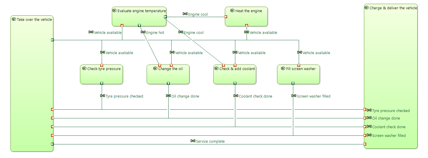
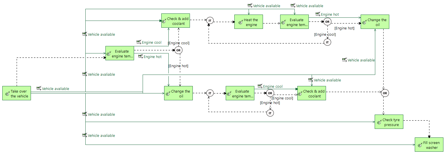
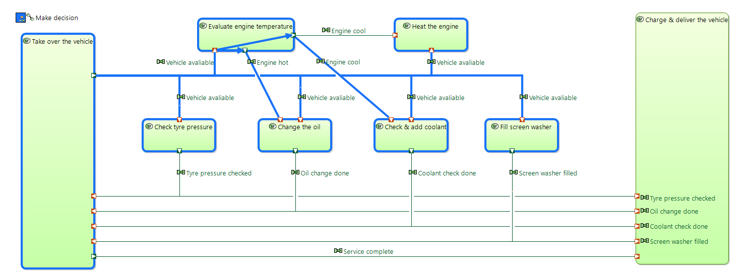
We’ve been reading this paper, which presents a model that appears like a greatly less complex version of our own:

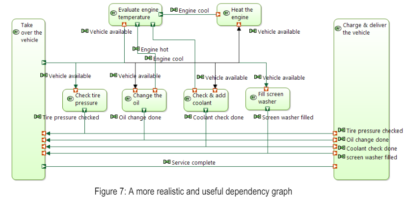
In this model, there are four functions which may need to be performed, and an optional ‘heat the engine’ function which is only performed if the engine starts off cool. The paper describes performing the required actions in a different order depending on whether the engine is initially hot or cool. It also states that “Capella does not provide the exact equivalent of SysML control flows
between activities” and that “sequencing order is mostly contextual (and sequence diagrams and functional chains are meant to reflect that)”.

If we pretend that this model is actually describing an autonomous car servicing system rather than a human performing these actions, where would a description of the logic to decide what order to perform each action in live, and what format would this be in? (There are far too many actions in our system to model every possible scenario as complete scenario diagrams like this paper does, so we would like to model small, concise scenarios and describe which one is prioritised).

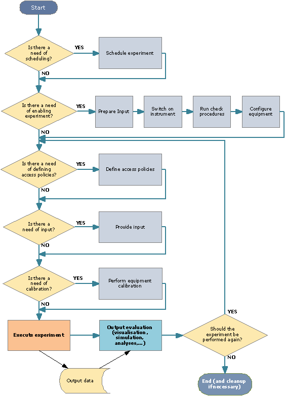
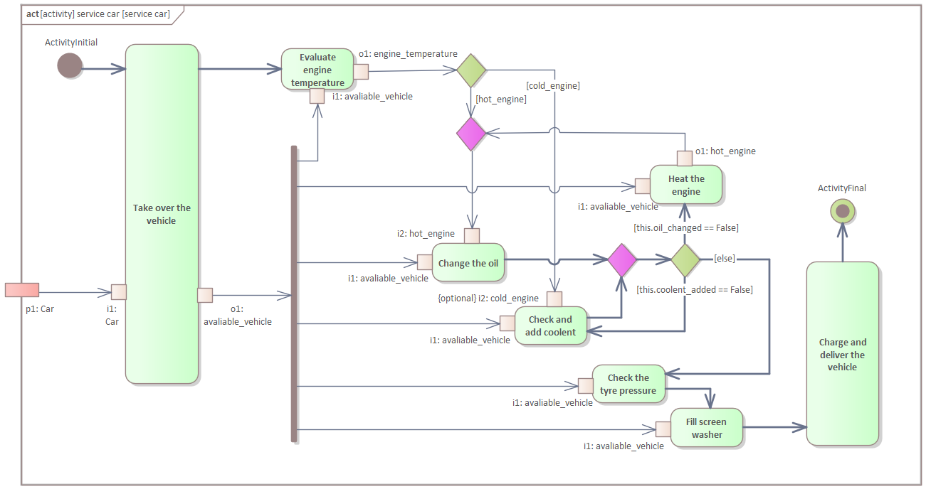
If I were using SysML, I would probably draw something like this for a low number of functions (actions), which describes the logic that the system uses to determine which function to perform first. I’ve made the control flows bold to distinguish them easily.
(I am assuming that the activities here set the system’s ‘oil_changed’ and ‘coolent_added’ variables to True once run, and these are initialised as False. I’m also assuming that performing the oil change will always take enough time to result in a cool engine.)


Only, ARCADIA doesn’t seem to have any ‘flowchart’ style diagram like this where intelligent decisions can be described.

There are also state machines in ARCADIA, which currently seem to be our only means of controlling a large number of functions and scenarios. Only, we are finding it tricky to define guards and triggers without variables in the model.

Are we going about this in the correct way? Please can anyone advise?

Thanks.

Hi @JackHutton,

With Capella it is possible to model control flows.

From the book Model-Based System and Architecture with the Arcadia Method by Jean-Luc Voirin:

There may, however, be cases in which it is necessary to specify the routing
conditions more precisely. This is then indicated by flow control functions, which
are intermediaries between the source(s) and recipient(s), responsible for controlling
the interaction conditions:
– to specify a simultaneous diffusion from a source exchange to several
recipients, we define a Duplicate function that transmits the same exchange items to
all the recipients;
– to specify the simultaneous diffusion of some of the exchange items to each
recipient selectively, a Split function that routes each part to a separate recipient;
– to specify selection of one among several potential recipients, a Route function
that transmits (most often subject to conditions) to each destination only some of the
exchange items received;
– to specify the combination of items of several exchanges from different
sources, a Gather function can be a single exchange item combining those received
from different sources;
– to specify selection of one source among many, a Select function that directs
only the elements coming from the selected source (most often subject to
conditions).

Also available on the Capella online help.

I hope that helps,
Hélder Castro

1 Like

Hi @JackHutton,

As you’ve discovered Arcadia does not have the equivalent of a SysML-like activity diagram. This is by design and for the reasons laid out in the paper you have referenced.

In Arcadia the complex interactions you are trying to model should, more appropriately, be done using Exchange Scenarios [ES] and Function Scenarios [FS]. These are very similar to SysML interaction diagrams. These will allow you to use guards and Combined Fragments to define the flow of control.

I also had this question before.
As a result have created Capella add-on that adds behaviour tree notation to Capella

You may know that behvaiour trees are used for control flow definitions
in game engines (Unity, Unreal Engines)
and robotics (ROS2)

See btree notation description for example here

Current add-on supports version Cappella version 5.2.0. You can find update site here

Thanks for the replies both.

@HelderCastro how would I specify control logic when using the route function? If I start with this diagram:

How to I describe which target function the route function directs the functional exchange to? e.g. the autonomous system should do the tyre pressure check first, then the screen washer?

@woodske Creating scenarios for every possibility is not practical in our case because we’re creating a highly autonomous system operating in an infinite problem space. Instead of having only 4 tasks like the example above, we have tens of possible tasks that we may perform where all the dependencies for each function may be met simultaneously.

Let’s say I have functions A, B, C, D, …, X, Y, Z, and the system can be in a state where it’s valid (according to the functional exchanges) to execute any one of these functions (similar to the example above where it’s valid to execute at least 3 possible functions at any time). I want to show that:

  • If you can do A or B, you should do B.
  • If you can do A, B or C, you should do C.
  • If you can do A, C, H, J, I and Z, you should do H.
  • etc.

You can see how some simple logic like:

  • If H available AND Z available: do H
  • else if C available: do C
  • else…

would be far simpler and easier than creating a scenario for the roughly (2^26)/2 = 33554432 scenarios that are possible from this.

I’ll try to give an real-world example that’s not what I’m actually working on:

If we suppose we’re modelling an autonomous driving car. We have the following scenarios:

  • Car stopped → green light → Car accelerates
  • Car stopped → pedestrian steps in front of car → Car stopped
  • Car stopped (at roundabout) → Another car comes around roundabout → Car stopped
    • many tens more…

How would we show that if the Car is stopped at a red light, then a pedestrian crosses in front of the car, then the light turns green (before the pedestrian has finished crossing), that actually the car should stay stopped? Or similarly that if the car is stopped at traffic lights on a roundabout and the lights turn green but another car is still coming round the roundabout that it should stay stopped? You could make a very large set of scenarios for every possibility on the road, but some simple control logic would be far more effective.

At the moment we’re considering state machines as our solution to this problem. This provides quite a nice way to control which functions you ‘do’ in certain states and specifies what states the system must be in for a given scenario to be valid.

But we still find that some things in our model are better described as flowcharts. If you have a system which follows this code structure:

  • If A:
  •  If B: do X
    
  •  else: do Y
    
  • Else if B: do Z

then you need three separate scenarios to express this simple logic. If you have a structure with even more conditions and functions, it becomes more and more incomprehensible when expressed as scenarios.

see short demo of Btree usage for control flow definition

Additional tool we’ve created to helps to define states for functions
Also we use functions state on functional scenarios

Hi @dsryzhov,

Thanks for highlighting this. I did spot this before I posted this question, though I’d like to first understand what the ‘correct’ approach to modelling intelligence is within vanilla ARCADIA is before considering add-ons.

I agree though - behaviour trees would be a suitable solution to this problem.

I’ve been looking at sequence flows on a functional chain diagram that do something similar to flowchart logic. I think this is a correct description of logic that determines which of the two scenarios described in the paper should be performed:

Is this sensible in ARCADIA though? A few points that make me unsure:

  • The functional chain diagram becomes a mess:

  • You cannot select unconnected routes through a functional architecture when defining a functional chain. i.e. two functions are executed in sequence but do not provide/require a dependency from one another.

  • This diagram could be simplified by hiding the functional exchanges (save them for the XAB) and just showing the sequence links. Only, you cannot initially create the diagram this way since it is owned by a functional chain.

@JackHutton,

From the paper and from figure 7, it it not possible to identify specific sequence of events. For this it is best to work with exchange scenarios as suggested by @woodske .

I suggested to explore routing conditions, for example, “Duplicate” that may cover the SysML fork model element.

However and considering your last diagram and using functional chains, it will not be possible to capture the exact sequence of nested operators that you would expect to capture.
To precisely capture the sequence of events ordered in time you may need to consider scenario diagrams and the use of nested fragments.

Thanks everyone,

In conclusion then, are we saying that modelling intelligence in ‘vanilla’ Capella is not something it was intended for? You are expected to model every possible eventuality as a scenario, even if this could mean there are many scenarios for what could be described in a single flowchart?

If we have a control process that an automated system follows like this one, which I quickly found online from here: Kennisgeving voor omleiding

Does ARCADIA expect you to model every single possible route (at least 25 different routes) through this as an exchange scenario without specifying this logic anywhere?

@JackHutton,

Arcadia does not impose any implementation constraints or rules.
It is a decision to the architect/systems engineer to decide how best to capture and present the architecture to the different stakeholders.

For example, you can capture a scenario for a “sunny day” where every actions occur as expected, and some other scenarios for “rainy days” or what if. That is, what happens is a failure occurs?
Several scenarios describe different situations that will eventually describe a capability.

The diagram above can be captured with a single scenario, if you wish.

I hope that helps,
Hélder Castro

In fact you can use statecharts for algorithm desciption in flow chart style. For every action you create separate state with to do pointing to action definition. and output transition without any triggers and guards. When action is complete transition will trigger and next action will be started.

I’ve added possibility to add existing actions(function) to statechart via drag and drop that
create new state with the same name as action and set to do linked to this action.
And tool in the pallete that create new state with linked new action.
The approach is the same as the behaviour tree demo.