Hi all, I’ve been using Capella for a very short time only and I don’t really know how to model a mechanical mount between a robotic arm and a mobile platform. This topic is similar to this one but I can’t find a way on how to use the same approach.
I’m using MBSE and Capella to model the integration of a robot arm and a mobile plaform, both currently existing and working seperately. The focus is on the integration itself. The basic idea is mounting the arm on top of the platform.
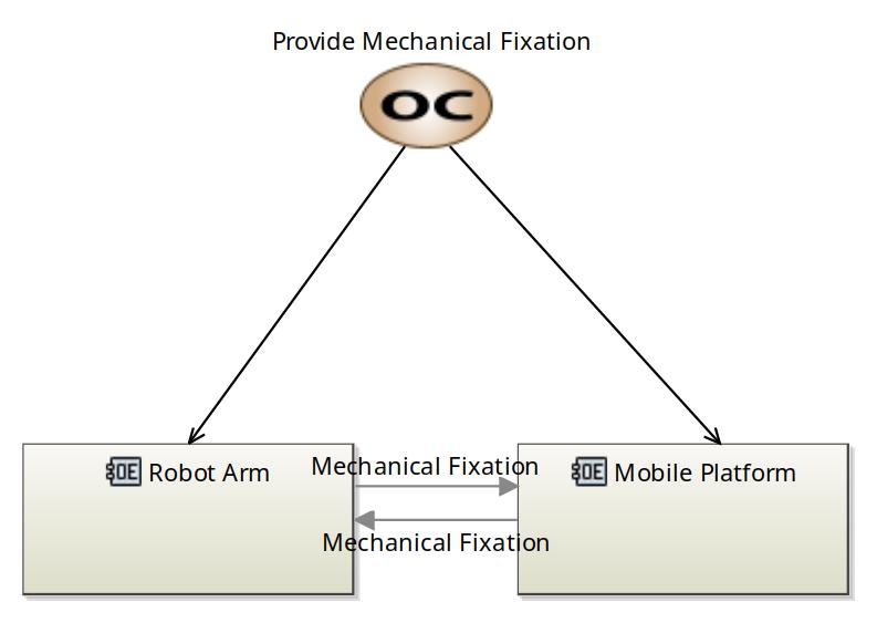
Also, I added a “Communication” link between the entities as a Mechanical Fixation. Would this be a good approach?
I tried a few options to model this situation but I don’t feel comfortable with any alternative even at Operational Analysis level.
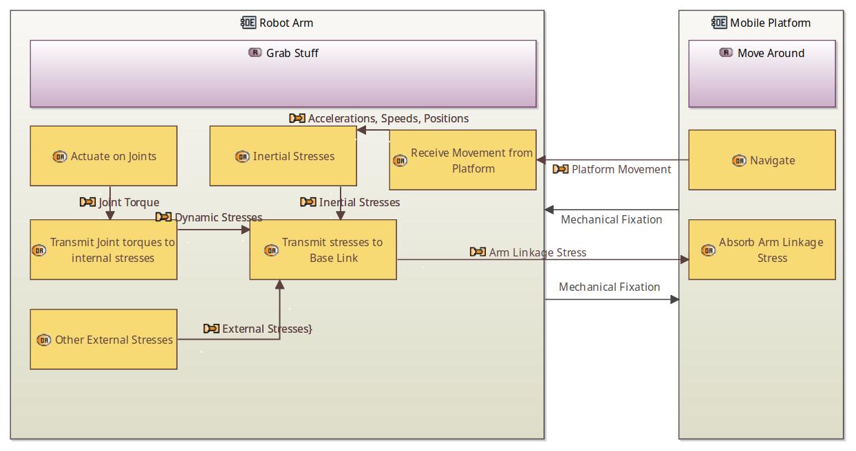
Alternative 1:
In this case, I try to set it up using a “dynamic physics model” approach. The platform imposes the speed and movement to the base of the robot arm and in return gets the forces and torques at the joint.
It doesn’t seem a good option for me because it looks quite detail to me, this approach might be more part of a logical or even physical specific design level. It’s way too restricted if, for example, the mounting solution is not rigid but is an articulated linkage or if you are even modeling compliance in it.
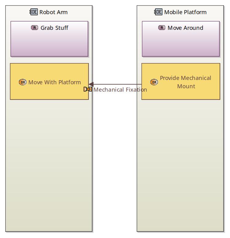
Alternative 2:
This is the most simple, just allocating “Provide Mechanical Mount” activity to the platform and “Move with Platform” activity on the arm. This looks quite better in short, but what should the exchange between those be? I used “Mechanical Fixation” but I don’t like it. Maybe I could use “Mechanical Force” but anyways, the exchange should happen in both directions (like Newton’s 3rd law). Also, I don’t think might be good practise to use “Force” concepts in Operational Analysis
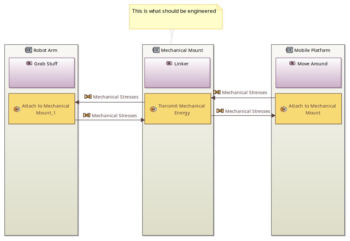
Alternative 3:
Defining the mechanical mount as an entity itself. This looks even easier to follow but from my understanding one shouldn’t talk about the engineered system at this stage, so this shouldn’t propagate good to the next design stages.
Any comments on this topic would be really appreciated.
Thanks
First a side comment: I think that your Operational Analysis is not correct. What you are drawing belongs to the Logical Analysis level. At the level of Operational Analysis the robot arm should not even appear. It will appear as a black box at the System Analysis level.
As for mechanical and control linkages, did you take a look at the Railroad Crossing Tutorial? While most of that tutorial is devoted to the control, there is a some detail on the mechanical support, motion, powering, and control of the gate (raising and lowering it).
Going back to Operational Analysis. You should start with capabilities, such as
- Hand the coffee cup to the customer
- Provide safety for customer
As you dig into the model levels, the mechanical constraints and flow of forces would show up at the Logical Level
It might be that it’s not the right tool for the job, or it’s at the wrong level of abstraction.
If it’s simply the modelling of a mechanical fixture, why use Eclipse Capella? An MBSE tool is about multidisciplinary architecture design and analysis; something that I don’t think your task needs. Instead, you might identify your measures of performance and constraints, sketch/mock up some concepts or prototypes, and use dedicated CAD/FEA tools along with Excel/hand calcs and any relevant standards (e.g. EU Machinery Directive) to design a solution.
If you want to model a system, then the Operational Capability is the value that your system delivers to the end user/customer. “Provide Mechanical Fixation” is a low level function that you’d allocate for a structural element; it’s not a capability delivered by the system to the end user. At Operational and System Analysis levels, it should be still black-box and solution agnostic, i.e. the internals of the system (such as structural elements) are completely hidden at this stage.
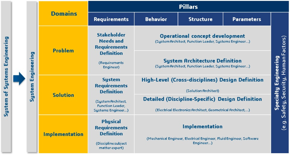
Compare it with MagicGrid; You’re still in the Problem Space. You’ve not yet entered the Solution Space.
Thank you both for your very quick replies! I’ll reply to both comments here together. Your suggestions really help me understand MBSE better.
This is basically what I’ve been doing:
I’m using Capella because, in fact, what is being designed here is the whole integration between the arm and the platform: mechanical integration, electrical powering of arm (at the moment it’s connected on wall outlet), communications, software and control integration, etc. I only showed the mechanical integration as it is what is confusing me the most, but I may have doubts in many aspects but this helps me a lot on those too. I think MBSE should apply well in this case, as the system being engineered should allow a full integration of the robots and, mainly, I’m aiming to learn how to use MBSE in general for other future projects related to mechatronics.
In this sense, as both the robot arm and the platform exists already, but each of them work independently on their own tasks and space, I thought they should be external entities on the Operational Analysis as what the user mainly needs is to “mount this specific robot arm on this specific robot platform and make them work as a mobile manipulator”. So, in this sense, I thought that the system being design (I understand it’s the black box at System Analysis) is "everything that needs to be engineered to accomplish this full integration (mechanical, electrical, software, etc.)
I saw the Raildroad Crossing Tutorial, but I will take a deep look again at the mechanical detail mirkov has pointed out. After that, I might try to think of my system in a more abstract way at the Operational Analysis Level and see if that flows better.
Thank again you for your commetns.