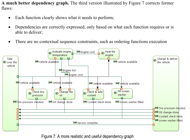
Hi, I have seen the functional modelling approach of ARCADIA and its principles in the book “Model-based system and architecture Engineering with the Arcadia Method” by Jean-Luc Voirin and the approach described in the paper “Simplifying (and enriching) SysML to perform functional analysis and model instances” which states with the ‘oil change’ example that dependencies should be modelled instead of sequences (in the Dataflow Diagrams - or dependency graph). Those dependencies would allow one to describe sequences of specific instances of executions of the functions through these graphs using either functional chains and scenarios.
Considering that, I have avoided modelling common resources such as electrical energy, hydraulic power, authentication for access and others because, if I did so, I would make my diagrams impossible to read - since I would have to connect “supply energy” to each and every function which depends on electrical energy to execute.
My question is: Is there any good approach to model such functions? I have thought about this and I think that maybe if I carefully only display the common resources on very specific diagrams (views specific for that purpose), I could model them without getting into a huge mess.
Anyway, I would be glad to hear about any known good practice for modelling such common resources in ARCADIA/Capella and if it has been applied successfully.
This excerpt contains the recommendation I mentioned on the original post.
(from: “Simplifying (and enriching) SysML to perform functional analysis and model instances” by Jena-Luc Voirin, Stéphane Bonnet, Daniel Exertier and Véronique Normand)
Hello Guarita,
I think that your approach to have dedicated diagrams to describe such functions and flows is the good one. I applied the same one on a complex model where each function had several “supports” flows (electrical power, service fluids …).
However you don’t necessary have to describe such exchanges on all Capella perspectives.
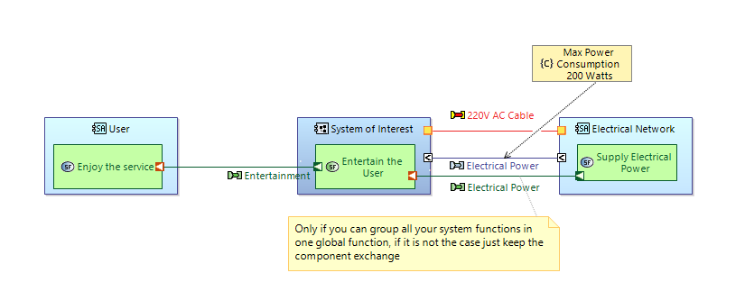
to give you an example for electrical power:
- in SA perspective you can only represent one global component exchange with the electrical network to apply a constraint/requirement on the maximum power consumption of you system
- in LA or PA perspective you will probably want to describe which components/functions need electrical power in order to evaluate/allocate the power budget imposed at SA level (and verify it through a dedicated view point).
- If our system is a PC, at SA level you can just give the overall consumption target, and in the logical and/or physical architecture allocate the power budget for the CPU, GPU, chipset etc.
hope that it helps!
Simone
Simone, thanks for the answer! It is indeed a very clean high level view for electrical power supply you provided! But I understand I would have to use categories to make it as clean as it is in your sample diagram since I’d have multiple ports on both supplying and consuming functions (at least one for each leaf consuming function).
That seems to be a good strategy.
I still do not use specific viewpoints to gather the consumption data but it would be interesting to.
One thing I used to consider external/internal power sources was to define a “manage power sources” function connected to an external “supply energy” function and an internal “generate energy” function.