Great! and thanks for your comparison wit flowcharts.
I also had quite a lot of experience when I tried to model reactive behaviour in Capella using only functional decomposition. (without statecharts). Statecharts are great in this but add additional level of complexity to modeling.
Using only sequence links on functional chain makes it impossible to visualize on architecture diagram AFAIK? If I don’t have any data flow between e.g. Sequence/AsynAction functions, how to visualise their dependencies on architecture diagram?
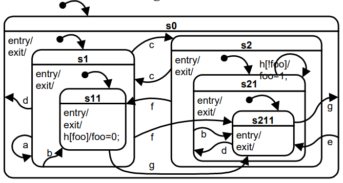
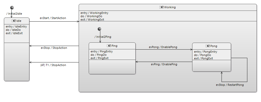
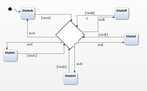
I’m not really sure here. FSMs can be quite complex leading to some “spaghetti” design, this is why HSMs has been introduced. How would you design e.g. following state machine as BTrees notation, as additional complexity you can add some guards and actions to every transition, plus some /entry, /do and /exit actions to every state and maybe some deep history to S2 too (then you also need s212 additionally
As I understand control flows should not be used on data flow diagrams.
I undestand this approach as mixing control and data flow results in spagetti diagrams.
Using BTree control flow can be visualized on data flows as composite functions (implicit declaration)
By the complexity I meant here not FSM\HSM notation. It’s another question.
I meant here that for defining behaviour you need two hierarchy “functional” and statechart and update them in parallel. With BTree you use only one - functional hierarchy. It’s much easier.
I will create BTree for this statechart for example
It’s quite new and not elaborated yet. For example it’s not possible to create control flows on architecture diagrams. Control flows are part of functional chains. So you always need to add a functional chain to define a control flow. And only after that it’s posiible to show it on architecture diagram. It’s what I mean by additional complexity in usage. For example on SysML activity diagram you can create data flows and control flows easily.
What you consider “complexity in usage”… is that there is an order to perform tasks (which is defined by Arcadia) and that drives the engineer step by step into defining the architecture, which in fact diminishes his usage complexity. But when you want to do different tasks, or want to do tasks in ways that are not those that are supported by the method and the tool, well, it becomes a little bit more complex That’s why you can extend Capella to new practices.
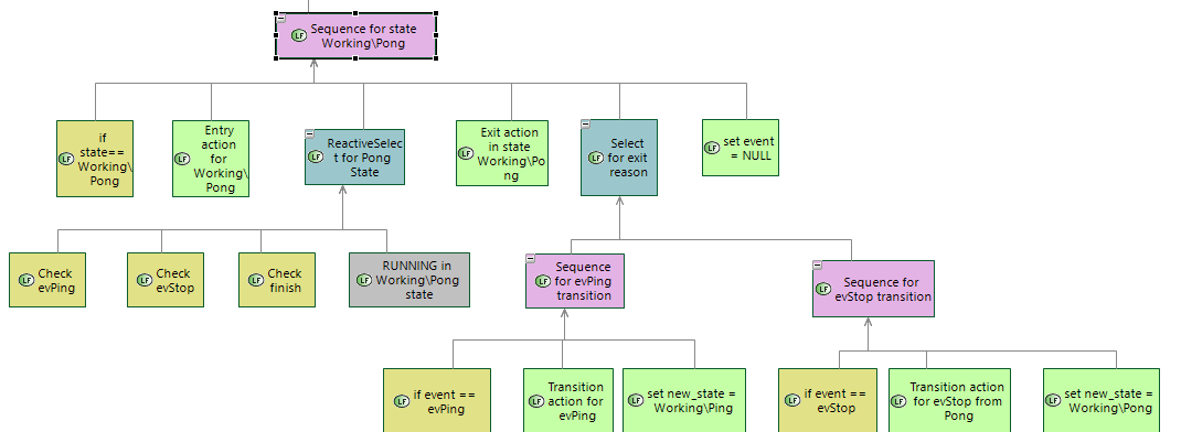
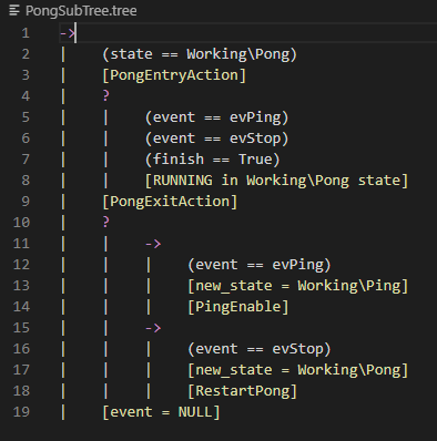
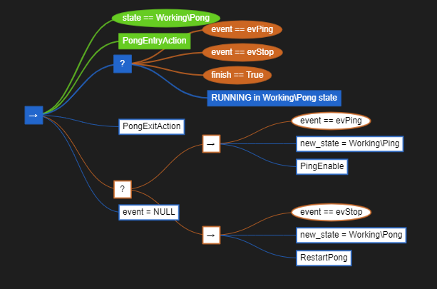
Let’ start to analyze BTree in below to up sequence and look at BTree part for Pong state.
Based on this state we can understand standard structure for low levels states processing using BTrees.
First sequence contains all step executed in Pong state. It starts when Pong state is transitioned to from some other state and ends with SUCCESS when Pong state is leaving for some other state.
Execution starts from condition checking (state == Working\Pong). After that entry, do, exit actions are executed. After exit action the reason of the leaving is analyzed and on transition actions are executed, and new stated is set.
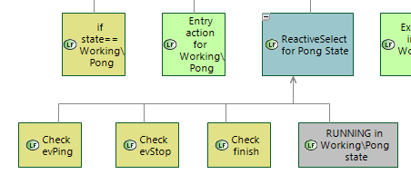
In state (do) action is executed asynchronously with a ReactiveSelect node. This node checks several conditions and if they all returns FAILURE sends tick to the “in state action” (grey one). “In state action” starts executing asynchronously and after start returns RUNNING result to the ReactiveSelect node. It also returns RUNNING to the parent sequence and so on. If some condition returns SUCCES to ReactiveSelect then it stops execution and returns SUCCESS to the parent Sequence. After that next child of parent Sequence is executed. Finish condition is a way to stop Pong executions from parent BTree, for example on some event that is handled by high level states.
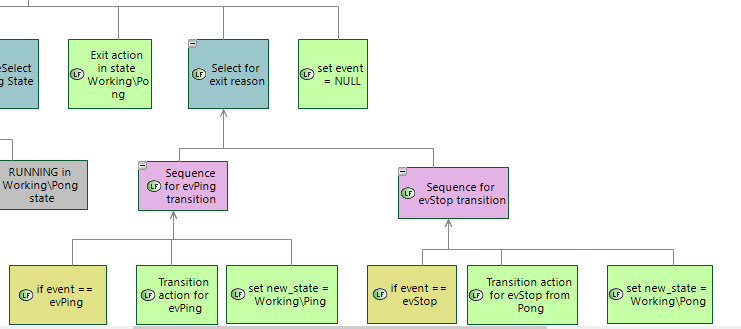
Actions on transitions are executed using Select for exit reason function. It has two sub functions: sequences for evPong and evStop events. For example if evPing event is received transition action for evPing event is executed. Aftre that new_state is set to Working\Ping state.
if function Select for exit reason returns SUCCESS last function in Sequence is executed: set event = NULL. It means that event was handled.
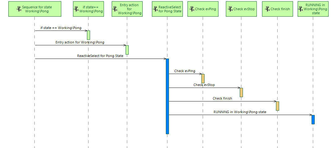
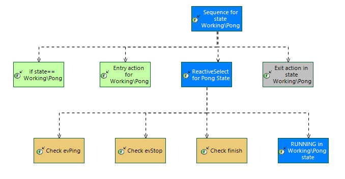
On the first BTree tick the following sequence of nodes are executed:
Sequence for state Working\Pong -> RUNNING
1.1 if state == Working\Pong -> SUCCESS
1.2 Entry action ->SUCCESS
1.3 ReactiveSelect for Pong State -> RUNNING
1.3.1 Check evPing -> FAILURE
1.3.2 Check evStop -> FAILURE
1.3.3 Check finish -> FAILURE
1.3.4 RUNNING in Working\Pong state -> RUNNING
after their execution RUNNING result is ruturned to the parent node (starting from 1.3.4 to 1.3 to 1.)
On the next BT tick the folowing sequence of nodes are executed
Sequence for state Working\Pong -> RUNNING
1.1 ReactiveSelect for Pong State -> RUNNING
1.1.1 Check evPing -> FAILURE
1.1.2 Check evStop -> FAILURE
1.1.3 Check finish -> FAILURE
1.1.4 RUNNING Workig\Pong state -> RUNNING
after their execution RUNNING result is ruturned to the parent node
and so on until some condition check inside ReactiveSelect not return SUCCESS result.
For example if evPing event is received ReactiveSelect is finished with SUCCESS result and exite action is executed
Sequence for state Working\Pong
1.1 ReactiveSelect for Pong State -> SUCEESS
1.1.1 Check evPing -> SUCCESS
1.2 Exit action -> SUCEESS
1.3 Select for exit Reason -> SUCCEES
1.3.1 Sequence for evPing transition -> SUCCESS
1.3.1.1 Check evPing -> SUCCESS
1.3.1.2 Transition action for evPing -> SUCCESS
1.3.1.3 set new _state = Working\Ping -> SUCCESS
1.4 set event = NULL -> SUCCESS
Somethink like functional scenarios and Functional chains are nedded to visualize BTree execution scenarios like this one.
It’s not possible to use stanard Capella tools to show the same information now.
I think that functional scenarios and functional chain diagrams could be specialized by viewpoint to show calls based on parent-child relationships.
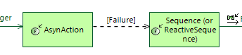
We can’t use functional scenarios because there is no functional exchanges betwee parent and child functions. New viewpoint could add additional edge type to the functional exchange scenario diagram to show calls between parent and child functions. Below is an example. In this case I used functional exchanges to show “messages”. It could be possible to use parent\child relationships to show call messages. Also information about call result is also needed.
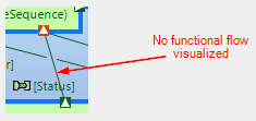
On the same principle new edge type can be added to functional chains diagram to show parent\child relationship between functions. In this example I use sequence link to show call between parents and childs. Also information about execution result should be added to functions involvements.
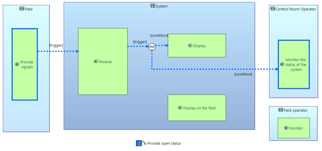
Information from such functional chains could be overlayed on functional breakdown diagrams like in this example:
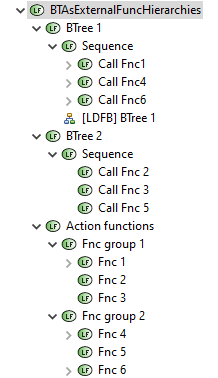
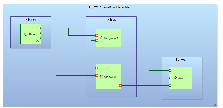
It’s possible to create BTrees as part of Logical Functions package but outside of functional decomposition. I mean that “atomic” functions could be defined as a separate clear “functional decomposition” hierarchy. They can be grouped by any principle. And composite functions of BTrees with execution semantics are not mixed with grouping functions of clear functional hierarchy.
BTrees are created in separate branches of functional decomposition. In this example there is clear functional hierarchy in Action functions. Atomic functions in this hierarchy is grouped into two functional groups. Two BTrees are defined as a separate functional hierarchies. (BTree1 and BTree2).
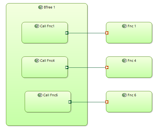
BTrees are using atomic functions from “clear functional hierarchy” via Functional exchanges.
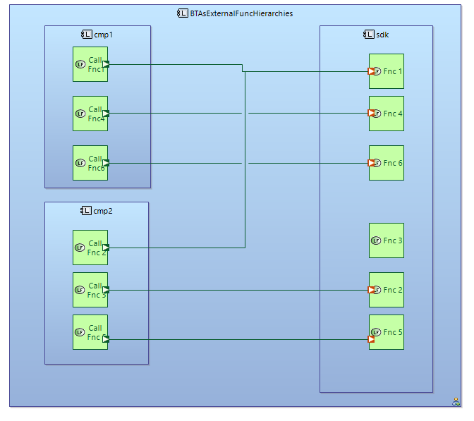
Leaf-functions of BTree and atomic functions of clear functional decomposition could be allocated to different components.
What just confirms that trying to replace HSM notation with BTrees makes rather not too much sense If then flowchart < BTree < HSM is true and Capella provides mode/state machines notation, what would be the benefit of having BTrees? Perhaps figures 2.3 and 2.4 in https://arxiv.org/pdf/1709.00084.pdf are the answer here, but I’m not so sure if this HSM couldn’t be designed in a bit more compact way, e.g. ‘choice’ and ‘event guards’ could be used to simplify transitions from all states to all states on given state event, preventing such “spaghetti of transitions”:
I think we need to differentiate between visual notations and model structure. By model I mean element’s structure that we see in model browser.
I think from model structure point of view BTree notation outperforms HSM.
it’s more simple
it’s more scalable
it results in modeling performance
HSM has more compact visual notation. And it’s commonly agreed that this visual notation is great for understanding when behaviur is quite simple. But when behaviour becomes more complex this visual notation stops working. In general it’s possible to create another visual notations for BTrees, that are more compact. Even tree structure can be much more compact (see XMind templates for example)
Disadvantages when using HSM from model structure point of view
behaviour via HSM can’t be defined without creating components
atomic functions need to be defined in a separate functional hierarchy (before or in parallel with HSM)
State machine diagram does not provide tools to create new functions. So you need to use different diagrams to define functions
before using in statemachines functions are need to be allocated to components.
mapping between elements from functions to states and transitions is implemented via dialogs (slow perfomance)
I would say that it;s hard to create HSM with more than 3 levels visually
Advantages of BTree from model structure point of view
BTree as part of functional decomposition organize it in a good and readable manner
it’s possible to create BTree using only one functional decomposition diagram
it’s possible to create textual DSL for BTree in which in one hierarchy control flow and data flow can be defined (results in modeling perfomance)
I see several possible ways how to reuse BTrees in Capella
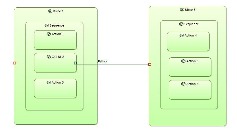
In BTree notation it is possible to include into BTree another BTrees by reference. Included BTrees are activated by ticks received from the parent BTree. In other words parent and child BTree control flows are connected. At the same time leaf-functions of BTrees could be connected via data flows.
This use case is different to the one where two independent BTrees are communicating. In that case leaf-functions of one BTree aer communicating with the leaf-functions of another BTree via data flows (not control flows). Tick cycles of this are not connected.
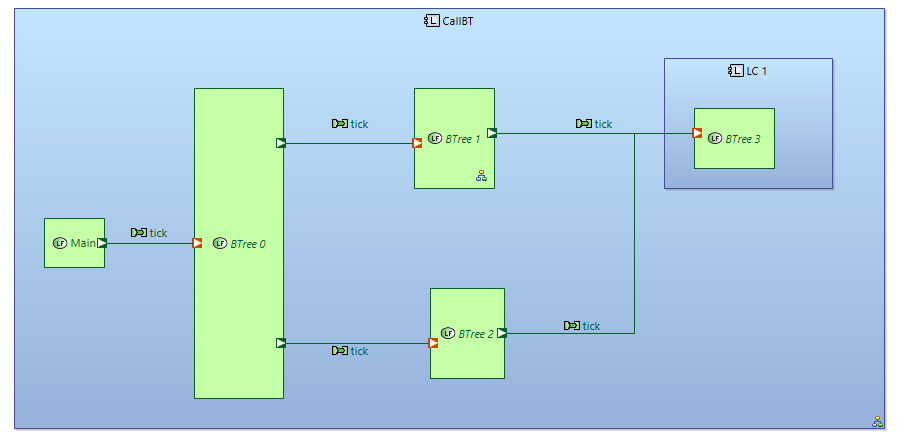
One possible way of reusing BTree is to use REC\RPC to include reusable BTree into the parent BTree. It will result in a physical copy of reusable BTree inside parent BTree. I don’t like this way for BTree “inclusion”. It will result in big BTrees.
Another way is to use reusable BTree as a stand alone BTree and connect to it via functional exchange link. I think it would be correct to use functional exchange from calling function from parent BTree to high level composite function of reusable BTree. In Arcadia it’s not correct to use ports in composite functions. But I think for BTree notation it will be the right solution. Semantics of composite functions in Arcadia and BTree notation is different that can result in different rules.
Every BTree composite function needs to have input port for external ticks.
This appoach is compatible with other model parts\representaions in Capella.
Reusable BTrees can be duplicated via REC\RPC mechanism as stand alone BTrees (without physical inclusion into parent BTree). In many cases you will need several instances of BTree to be able to connect leaf functions of different instances with different external functions. In this case such an approach can be used.