Using behaviour three notation for behaviour description in Capella in comparison with statechart notation

Thank you for the answer. I’ve send an e-mail to labs@mbse-capella.org.

Now it’s possible to decompose big BT into smaller one. When used inside functional decomposition it results in creating composite functions with sub BTrees.

Currently it’s possible to create Behaviour Tree element\diagram for any function (composite or atomic)
In this case BTree is used to add behaviror description for a function based on it’s sub-functions.
As a result all execution semantics (sequence, paralell, fallback and so on nodes) are contained inside behaviour tree element. Parent function contains only result atomic functions defined during BT creation.

If the Behavior Tree become too large it’s possible to decompose it to several sub Behaviour Trees.
Any composite node of BTree can be selected on diagram and transformed to separate Behaviour Tree

In case BTree element is contained inside functional decomposition when sub BTree is created
a new sub function is created. BTree is placed inside this sub function. All functions used in this BT is moved to this new sub function.

Demonstration how BTree is decomposed into sub BTrees with functional decomposition

Moved execution order numbering from nodes to relations.

Also changed the way how node’ numbering is applied (Action 1, Action 2, …). Before these numbers were calculated inside parent node. And several “Action 1” can be created from different composite nodes. Now this numbering is global to behaviour tree and results in unique function names created from BT.

It seems to work after copying rds.* jars to ‘features’ and ‘plugins’ folders. What should be done with ‘artifacts’ and ‘content’ jars? Consider sharing it as a drop-in - it’d be more consistent with other Capella add-ons.

Good. I like that it works )

You can use jar files from updatesite plugin directory and copy them directly to dropins folder of Capella (jar from features folder does not needed in this case)

I agree that it’s more simple and fast way to install add-ons in Capella :slight_smile:
I think I will be able to create additional zip for “dropins installation scenario”

UpdateSite is a package technology that is used to install addition features to Eclipse (and Capella)
It can be used from Help > Install New Software
Typically updateSite contains a lot of features, subset of them can be selected and installed.
For example updateSite can contains several viewpoints some of them can be selected to install.

Working on defining a way to model “data transfer” between leaf actions of BTree
For BTree on component level there is no questions.
But for BTree in “atomic” function level I have

Capella does not have a goal to model behaviour of atomic functions.
If you we want to model intrinsic behaviour of atomic functions we need additional elements.

In Capella there is three levels of modeling

  • Functions, and Functional Exchanges
  • Components, and Component Exchanhes
  • Physical Nodes, and Physical links

Functions hides details of their implementation. Capella Data flow diagrams in fact does not show separate data flows explicitly. They show functional exchanges. That can contain separate input and output data flows.

If we want to model behaviour of atomic functions and data flows in detail between them we need one more level of modeling

  • FncBlocks and Data Exchange

On the diagram bellow FncBlocks are in orange. And data flows between FncBlocks are modeled explicitely.

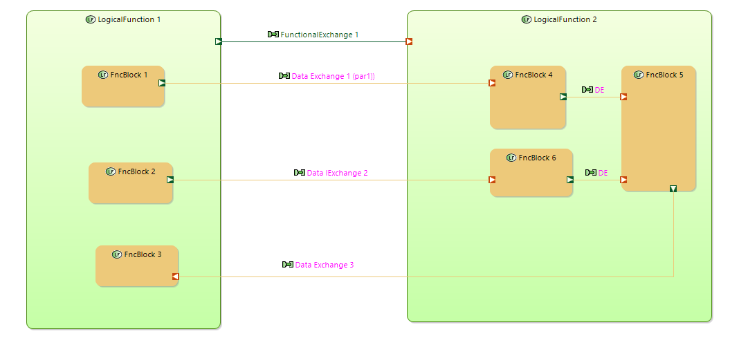
FncBlocks can be used to model implementation details of atomic function. FncBlocks can be decomposed to sub FncBlocks in the same manner as functions.

FncBlocks can be modeled separately from functions and “allocated” to functions in some stage.
On this stage FncBlocks are “packed” to Functions the same way as functions are “packed” to components. Another way to model implementation behaviour inside functions.

Functional exchanges hides data transfers. They can contains exchange item elements (in and out).
They are more like “function calls” with input parametes and out parametes. As a result data value transfer are modeled implicitly.

Data Exchanges can be used to model explicitly data value transfer between FncBlocks.
Several Data Exchanges can be allocated to one Funcional Exchange.

“Data ports” can be used to model each input\outpup parameters used in Funcional Block.

“Data exchanges” can be used to show explicitlly data transfers betwee functional blocks.

Before I tried to model internal behaviour of functions using sub-functions, data flows between sub-functions using functional exchnages, data ports using functional ports. But now I think that a separate level is needed. In this way new functionality will be compatible with “a Capella way”. Atoomic functions remains atomic. But if you need to model function in detail you can use aditional meta model and notation.

If BTree is defined for atomic function them Functional Exchange is used to “tick” behaviour tree of called function and used to provide input parameters for BTree. It also receives output result of tick (SUCESS, FAILURE, RUNNING) and output parametes of BTree.

Always used it for updates from remote repos, wasn’t sure that you can also install a local stuff :slight_smile:

I’d be careful here as it might lead to some misunderstanding regarding implementation of such function with functional blocks. Especially regarding data visibility/scope/encapsulation and its exchange mechanism. If atomic function is implemented as a procedure, function or method, how its functional blocks and data exchange between them should be implemented? Functional blocks seems to be closer to some design stage, thus a bit out of the scope of Arcadia methodology.

Arcadia and Capella already provide some concepts for modelling data that go way further but integrate well with functional exchanges. You may want to check the thematic highlight about Interfaces and Data modelling in the Capella Help.

I will try to explain by examples what I want to see on FncBlocks diagram

Let look at some functional block that should calculate output based on input

output = FncBlock2 (input)

a = f1 (input)
b = 5
c = f2(a, b)
output = (c, b)

using only ports (no variables)

using “variables” (or data objects betwee functions)

using variables and variable references

Data ports and variables can be typed by Capella classes.

This diagrams shows only data flows. There is no control flows here.
For contorl flow definition Behaviour Trees or Decision trees could be used.

In case of Behaviour Tree B, F1, F2, F3 will be referenced from leaf actions.
image

Why use different meta-model for modeling behaviour of atomic functions?

In this way Capella “atomic” function remains atomic and does not decomposed into functional blocks
In this way Statecharts and Behaviour Trees defined for components can used atomic function but not functional blocks.

In other words using different meta model makes main model compatible with Arcadia\Capella.

image

Atomic functions specify signature but does not specify how output is “calculated” from innputs
image

More over functional exchanges with Operation exchange type have control flow semantics but not only data flow.

Functional blocks specify how outputs are calculated and does not contains any control flow semantics.

We don’t want decompose atomic function 2 to F1, F2, F3. We want to allocate to components atomic functions but not functional blocks.

Data flows and data ports can be allocated to functional exchanges and functional ports. The same way as functional exchanges are allocated to component exchanges.

Not sure I understand well. But what is for sure is that functional exchanges in Arcadia represent dependencies between functions in terms of what is exchanged (data, mass, energy) and not control flows.

Your FcnBlocks remind me the Function Blocks defined by IEC 61499 standard:

image

This is clearly out of the scope of Arcadia, which doesn’t address the detailed definition of leaf functions behaviour.

I would suggest to create a new forum thread on this topic, and to differentiate the BTree (which can be useful without introducing this level of detail) and these FcBlcks (which could be useful indepenently of the BTrees).

I understand that defining behaviour of atomic functions is out of scope for Arcadia.
In IT projects where I mainly used Capella I needed to specify behaviour of atomic functions.

I think Functional blocks are similar to blocks from IEC 61499.

FunctionalBlocks can be used without BTree. I even created another viewpoint for their definition. I will create another topic on modeling atomic functions using functional blocks.

But BTree can be used to modeling control flow of functional blocks inside atomic functions. From this point of view they are connected.

There are 4 main use cases for BTree usage

  • in capabilities
  • in components
  • in composite functions
  • in atomic functions

Functional blocks can also also connected with ComplexValues in some way and my ComplexValue viewpoint I’ve created to define mappings between ComplexValues.

ComplexValue viewpoint helps to define mapping between intput and output parametes of functional blocks.

There is another notation where Functional Blocks is used. See xod.io
It’ a visual tool used to create programs for Arduino, ESP8266, ESP32.

In this tool data flows and control flows are modeled on the same diagram.
To model control flows (ticks) diferent type of exchanges are used. (in parallel with data flows)

Done and UPD ports can be connected. Some tick (from clock) can be connected to UPD port. Or some modificator (for example Loop) is applied to UPD port.

In more detail execution model of XOD is described here

Leaf actions\conditions in Behaviour Tree notation communicate over the Blackboard.
It’s a key\value storage global to Behaviour Tree that can be used by any leaf actions\condition.
Each Behaviour Tree has each own Blackboard.

Input\output pins are implemented over Blackboard by using the same name for ports.
Also Blackboard value can be set or read by any leaf function.

Behaviour Tree notation does not define visual notation for data flows diagrams.

Visual notation I’ve published before for data flows between Functional Blocks can be easily mapped to Blackboard objects

When Behaviour Tree is used with atomic functions data flows between functions are modeled by functional exchanges. Input\output pins send\receive not individual data but ExchangeItems that contains individial data that is called ExchangeItem Element.

In other words in case of atomic functions data pins are modeled implicitly by functional exchange pins and their ExchangeItem Elements. It can be interpeted as composite functional pins (typed by ExchangeItem) that contain data pins (ExchangeItem Elements typed by data types).

On the diagram below functional blocks are shown inside it’s parent atomic function.

In this diagram internal parts of the input port for atomic function is shown as 3 level port.
FunctionInputPort -> ExchangeItem -> ExchangeItemElement

Ports on the third level is typed by Classes and have directions (red - input, gree - output)

ExcgangeItemElements of atomic Function is mapped (delegated) to DataPorts of FncBlock.

Below is the demonstration of detailed behaviour specification for atomic functions.
Functional Blocks and Behaviour Tree are used for this specification.

Root FunctionalBlock is created inside the atomic function.
Behaviour Tree is created Inside the root functions block.

Control flow for atomic function is defined using Behaviour Tree
While BTree is created sub FunclBlocks are added to the root Functional Block.
FncBlocks can be grouped into any hierarchy and don’t depends on structure of BTree nodes.

Data ports and DataFlows between sub FuncBlocks are defined using new data flow diagram.

When diagram is created root FncBlock is shown automatically. On the border of the root functional block input and output ports of parent atomic function are shownn. For functional ports detailed structure is shown based on exchangeItems and exchangeItemElements specified for ports.
This ports are used for mapping (via delegate) between elements of functional ports data ports of sub FuncBlocks.

As mentioned, functional blocks as presented are part of design/implementation, not architecture anymore. Did you generate some code out of this or just defined internal structure of an atomic functions and later coded it by hand? If I had to define internal structure, I’d prefer to generate the code instead of redoing textual implementation, which means we’re close to implement some open source Simulink equivalent :wink: The notation of functional blocks is also a little bit troubling to me as both FncBlocks, F1 and F2 are just normal functions, so they shall exist somewhere in a functional decomposition. Just F3 is some abstract code element, also ‘b’ constant can’t be modelled as it’s not a function:

grafik

And some details of allocated exchange items/elements can be specified on interface level.

Nevertheless, your last video is very interesting, just a use case is not so clear yet, e.g. what should be the relation between actions and functions?

Yes. it’s design

This FuncBlock notation is 2 days old. So not yet )

Let’s look at an example from software engineering.
Take class A and define several functions inside this class. And define main function that implements control flow (business logic of this class) and execute other class’ functions in some sequences.

All of this function when executed also implements some control flow (but more technical one) : analyze input parametes, prepare parameters for external functions, calls external function, analyze results, create objects based on results and so on. I named this actions as functional blocks.
We don’t want to know about them in the main control flow (busines logic). We don’t want to subdivide functions defined in class.

In case of Capella modeling we want to have class functions to be atomic functions in functional decomposition. And used them in statechart\behaviour tree defined for component.

In othere words we don’t mix busines logic with technical logic.

In IT projects there are a lot of “technical” work and logic inside atomic functions. Data are prepared, services are called, mapping between different strutures are made. In our case software implementation was done by several subcontractors. They had not very good understanding of data architecture in our system. We needed to define a lot of mappings for atomic functions:
between input data and called services, services results and atomic function resul and so on.

I’ve created special viewpoint to define these mappings (ComplexValue Viewpoint). Aftre mappings are defined we needed some way to define control\data flow inside atomic functions and “attach” these mappings to blocks of this flow. We did decomposed atomic functions into functional blocks as part of functional decomposition and attached mapping to leaf small functions. I don’t think this is a good aproach as “business logic” mix with “technical logic”.