Synchronous calls with one or two FunctionalExchanges

It would say that name “Data flow diagram” is not semantically correct.
This diagram shows functional calls but not data transfers. I would rename it to Functional exchanges diagram.

If want to model data transfer visually (but not implicitly as part of FE) we need to add additional port type and exchange type: data ports and data exchanges. In this case we will be able to model as functions call (using FE) and data tranfers (using data ports and data exchanges).

Data ports and data exchanges can be allocated to function ports and functional exchanges the same way as functional ports and FE are allocated to component ports.

Let’s return to the question how to decompose LowLevelFunction when only one FE is used.
I really don’t like this way of introdicing additional function that unpack and pack data to ExchangeItem.

I would say that I don’t want to use exchangeitems between sub-functions. ExchangeItems are needed between functions that are allocated to different componenets. In this case ExchangeItems between functions are used to model function calls and will be added to interfaces between components.

When I want to specify internal behaviour of function using sub-functions I would like to use data ports and data exchanges for subfunctions. They will be typed by data types but not exchange items.
Data ports of sub-functions are needed to be mapped to input\output parameters of functional input port.

It’s also possible to show data exchanges between HiglLevelFunction and LowLevelFunction. It will show explicitly all data transfers that can not be shown explicitly using FE.

Hello,

I guess that “Dataflow” was chosen because the main characteristic of these diagrams is that they don’t show control flow, as it is the case for the already existing dataflow diagrams (DFD).

I agree that the name is misleading but not for the same reasons: it is because there may be other stuff than “data”. It should be renamed to Dependencies Diagram (which as the good taste of keeping the acronyms unchanged :wink: ).

FE represent dependencies between functions, and the data and mechanisms for sharing this data is provided by Exchange Items. In some cases the flow of data correspond to the direction of the FE (e.g. if you use a Flow-type Exchange Item), in others is kinda weird because the direction of the FE represent the call and not the return of the call (e.g. when you use an Operation-type Exchange Item as in your example). But by defining proper modelling guidelines and when everybody is aware of that, these concepts are useful in modelling detailed dependencies between functions and components.

I have a question. Who is dependent function in my example. HighLevelFunction or LowLevelFunction?
From the sync calling perspective I would say that HighLevelFunctions depends on the result of LowLevelFunction.

But if look at anotrher example with the sequence of of functions. Second function use the result of first function. In this case dependent function will be Second function.

FirstFunction → Second function

This two examples show ambuguity of FE visual notation. For different cases the same looking diagram will result in different dependent functions. Only FE with exchange mechanism define define dependent function. And it’s not easy to understan visually from diagram.

All above I can understand up to the moment when I want to decompose sync called functions.

Could you please make an advise how to correctly decompose LowLevelFunction?

May be FE should be shown differently for different ExchangeItem types? It will result in more clear visual clues about function dependecies. The most radical way to chenga direction of FunctionalExchanges for sync calls to show dependency of HighLevelFunction from LowLevelFunction.
The less radical wey is to use some dot style or two arrows for FE.

I think the right answer from the Arcadia point of view: You should not decompose function if you don’t plan to allocate subfunctions to different components. Am I right? We can call this level functional decomposition to be architectural level. If we want to do design and decompose functions inside the same component than it’s ok but it’s out of the scope for Capella\Arcadia.

And we clearly see from this example (decomposition of synchronously called function) that notation is not very good for function decomposition below architecture level.

No. You should decompose functions if it is relevant for you and if it helps claryfing what is expected from the system and component. There are also good practices that are related to the perspective you are working in: for instance, a System Function (in SA perspective) represent what is expected by the system as a whole, independently of its position on the functional breakdown tree in the SA. But in any case, there may be cases on which you decompose a function and allocate all the subfunctions to the same component.

I agree that it’s not the correct phrase about allocating to different components as a criteria to stop decomposition.
And I agree that level of modeling define level of granularity (system, logical, physical level).

From practice it’s not a good idea to decompose functions to the level when you need to allocate to component small sub-function from several functions. You should stop on previous level or define separate components for each function (and allocate all sub-functions to one component).

Can you share your thoughts about the correct way to decompose sycnhronously called function? I mean how to visually show return of output value?

Sometimes I understand that I should stop to decompose functions on some level. But need some way to specify behaviour of “low-level” functions, to describy what it should do in some formal way. I can do it by description. But it would be great to use modeling for this also I mean low-level functions should answer to question what system\component should do. But some formal notation should be applied to describe how this function need to be implemented if such requirements exist. I mean behaviour of the low level functions that should not be described by next level of function decomposition.

I need a model that clearly say what subcontractor needs to do (list of the low level fucntions) and how these low level functions should be implemented (their behaviour). I don’t want to lost “what” in “how” by adding additional level of function decomposition. But I want to be able to specify behaviour of functions if such requirements exist.

I can’t catch this fundamental moment of Capella usage.
And really need help to understand this moment.

In fact I have a feeling that operation call semantics should not be used in capella functional decomposition.

All examples of Capella usage show linear chains of functions where functional exchanges are used as data flows (not functional calls with data return)

More over Capella should not be used in call stack manner: Some functions calls another function, analyze result, call another function and so on. If call semantic is used than control flow will embeded into functional decomposition. And this should not be done in Capella way.

Calling semantics should be implemented on the components level that “enables” functions in some sequence based on states. When you model physical system many functions are enabled at the same time and exchhanges some flows. But it comes to software components it’s more common to think about software behaviour in terms of functions calls and call stacks. And I think it’s not the correct way of Capella usage. We need to model software in terms of “functionality” and thier dependency. Every functionality needs some data and provides some data.
All functions should have input parameters and should provide outputs. Inputs and outpus of different functions are connected to each other via functional exchanges.

What about Interfaces and Exhange items with type Operation. May be they should be used as a hint on mechanism how data is transfered but not define how functional exchanges are used. I would say they should not be used at all on architecture level. It’s a design decision how to provide data via operation call or via push or via pull. On the architecture level only data flows should be defined.

Some example to compare call stack with instance modeling

Function modeling in call stack manner (I assume it’s incorrect usage of Capella)

image

Function modeling as data flow (instance modeling).
We don’t model how this functions are called but only how they use results of each other. I assume this to be the right way to model functional exchanges.
Call hierarchy is modelid implicitly by functional hierarchy.

image

If LowLevelFunctions are implemented by another component than first component will have “calling” functions. As a result we will come to mixed example

I want to try usign second FE witn return semantic.
It will sync calls to be more explicite on data flows diagrams.

We may simply not to create opposite Interface for return FE

In this case it’s possible to decompose called function and show return result explicitly

Yes it needs additional FE that “clutters” diagram. But result diagram become more “data flow” like but not “function call” like. In this case data transfer occurs on all FE in the direction of FE. There is no reverse data transfers.

By adding some customization It’s possible to link direct and return FE by some link. In the same manner as it’s done for return branch on Functional scenarios.

The approach with return FE will result in the folowing diagram for previous example

Yes, return FE add clutter to diagram but makes it more explicit.

We can assume that functions in the above exampe are defined in different architecture levels:
On each level we have added new details.

HighLevelFunctions - defined in SystemAnalysis
MiddleLevelFunctions - added in LogicalArchitecture
LowLevelFunctions - added in PhysicalArchitecture

As always we can select between two strategy to procede with functional decomposition on the next level

  • decompose functions from previous level of architecture
  • add derived functions as subling functions (in this case which are called)

In different cases we will select different strategy for the next architecture level.

Let’s assume that we have defined behaviour of the system in SystemAnalysis via statechart and want to use this specification in LogicalArchitecture. We transition HighLevelFunctions and statechart from SA to LA and allocate functions to LC and place transitioned statechart to this LC.

If we want to reuse statechart from SA we can’t decompose HighLevelFunctions. And we need to add MiddleLevelFunctions as sibling (derived), call them from HighLevelFunctions and allocate to a new sibling component.

In this approach functions defined on the previous architecture level remains “atomic” on the next architecture levels. Behaviour in forms of statecharts can be reused on the next levels and formulated in terms of functions from previous levels.

Statechart, defined in SA will remains the same in LA and PA. It can be enhanced with some detail but it will continue to use HighLevelFunctions

If we will decompose HighLevelFunctions on the next stage into MiddleLevelFunction (LA) and LowLevelFunctions ¶ we will not be able to reuse behaviours specifications from previous architecture levels and need to reimplement behaviours in terms of ML or LL functions.

Behaviour can be implemented via orchestration (some statechart call functions in predefined manner) or via reactive pattern (several components interact with each other via reactive principles).

Behaviour in SA can be defined via orchestrations of HighLeveFunctions but “implemented” on the next architecture using reactive pattern. In this case reactive behaviour shoud “satisfy” to behaviour specified on the previous architecture stage but not to be decomposition of it. In this case behaviour specifications from previous stages should not be reused. And HighLevelFuncions could be directly decomposed.

As a result in some use cases of Capella usage we will come to the following functional decomposition in PA level.

All functions shown in this diagram will be “atomic” (not decomposed).

We want out behaviours (control flows) are defined on different levels: in terms of HL functions, in terms ML functions and in terms LL functions. HighLevel behaviours start middle level behaviours, and middle level behaviours start low level behaviours.

  • SA: behaviour of system in terms of HighLevelFunctions
  • LA: behaviours of HighLevelFunctions in terms of MiddleLevelFunctions
  • PA - behaviour of MiddleLevelFunctions in terms of LowLevelFunctions

How we will do this? Let’s look at Logical Architecture level.
In LA we need some way to specify behaviour of HL fucntions in terms of ML functions.
In LA we will allocate HL fucntions to different LCs. And we will place system statechart to Logical system.

We will define new MiddleLevelFunctions and allocate them to some ML components. After that we are able to add FE between HL functions and ML functions.

And now we need some way to specify behaviour of HL functions in terms of ML functions.
We can’t decompose HL functions as our “system” behaviour is formulate in terms of atomic HL functions. But we need to decompose HL functions to be able to define it’s behaviour in terms of ML fucntions. We need to call ML functions in some order.

If will try to define statechart for High Level Components we will not be able to use ML functiosn from sibling ML components. We can only use functions allocated to the same component where statechart is placed or from it’s subcomponents. If we will decompose HighLevel functions we will be able to define their behaviour via statecharts of HighLevel components. But in this case we will obtain unvalid main statechart for Logical System that is formulated in terms of HighLevelFunctions.

So we can’t decompose HL functions but need to decompose them to define their behaviour. Paradox.

To solve this paradox I’ve introduced FncBlock notation to be used to decompose atomic functions to smaller blocks without decomposing them into sub functions.

FncBlocks are similare to Capella functions. The main difference that data transfer are modeled in more detail. FncBlocks are connected via data exchanges and data ports that can be typed by any DataType.
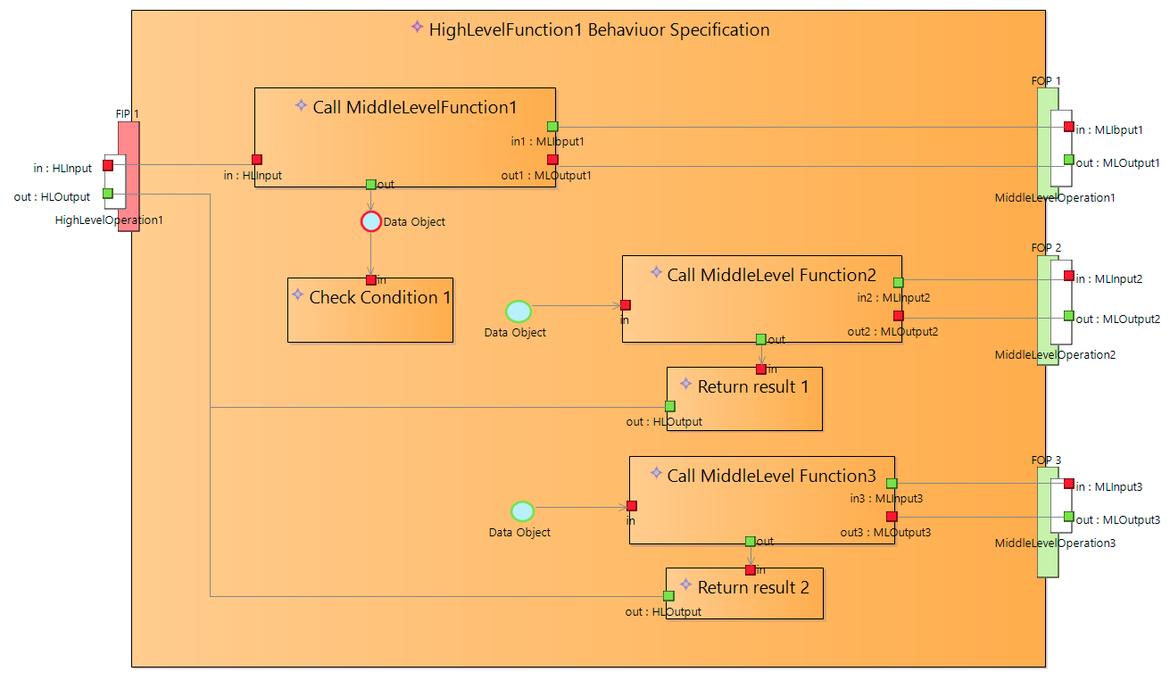
External data ports are mapped to ExchangeItemElements of atomic function ports.
Diagram above defines data flow between FncBlocks.

Using FncBlocks we can decompose any atomic functions into smaller blocks and define behaviour based on these smaller blocks. To define behaviour (control flow) we can “use” FncBlocks from statecharts, BehaviourTrees and activities. What way we use to define behaviour depends on the behaviour type. In all cases we define behaviour in terms of defining control flows of FncBlocks.

FncBlocks was introduced during my reasearch of applicability of BehaviourTree notation for defining behaviour in Capella. But they can be used not only with BTrees but with statecharts also.
More information about using FncBlocks with BehaviourTrees can be found staring from this post in the BTree topic

Full example of specifying behaviour of “atomic” function HighLevelFunction1 using FncBlocks

It includes specification of FncBlocks and dataflows

and “control flow” that specofy how FncBlocks should be executed (in this case using BehaviourTree)

Result specification model for behaviour of HighLevelFunction1

Conditions, calls and returns FncBlocks are groups to sub FncBlocks by hand.
Behaviour Tree includes involvements of FncBlocks that has the same names in model tree.

Flowcharts also can be used to define control flow for atomic function behaviour specification.

Flowcharts and Behaviour Trees are two different ways that can be used to define control flows for FncBlocks.

Below is a demonstration how flowchart is used

  1. Behaviour specification element is created for atomic function
  2. Flowchart is created to define control flow and create FncBlocks
  3. Data flows between FncBlocks are defined using separate dataflow diagram

Actions and decision on flowchart are involvements of FncBlocks.

It’s also possible at first define FncBlocks on data flow diagram
and after that use them on Flowchart or BehaviourTree (via Drag and Drop) to define control flow.