Good day,
I’m a relatively new user of Capella and the Arcadia method and am new to this forum.
I’m currently modelling a relay-based system which implements simple combinatorial logic and nothing more. Although my primary objective is to model the external interfaces of the relay-based system, it got me thinking about possible ways to model the interior of the system too, which is made up of a number of identical cabinets with numerous relays mounted on them and standardised terminal interfaces for the various kinds of inputs and outputs. The cabinets implement combinatorial logic thanks to interconnections which are made between the various terminals of the relays, including current input to the primary relay coil and numerous pairs of normally open/normally closed contacts.
This means that you have numerous relay cabinets made of exactly the same components which differ only in their interconnections, and as a result perform completely different functions. When decomposing a logical function, it becomes clear that even the most elementary logical function (and, or) cannot be allocated to a component. An “and” function for example may be spread across numerous cabinets because it involves several relays mounted on different cabinets. It seems that there is therefore no way of creating an allocation link between the functions as specified and the involved equipment (except on a very high level by saying that logical functions 1-100 are implemented by relay cabinets 1-5 as a single block). As soon as you break the problem down within the Arcadia method, the functional and physical aspects become decoupled.
The only other option I can see is to change what is meant by the term “function”, such that the implemented functions become “compatible” with the involved equipment. This would mean translating the functional description into elementary “switching” functions rather than logical functions. However this could mean that the functional description is biased according to the physical implementation.
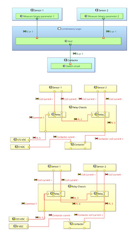
I’ve put some diagrams below to illustrate. The first is the function to be performed (“and”) and the second is its implementation with a given convention for the relay contacts. The third is an “or” function using exactly the same equipment, same IO ports, only differing in physical links between contact points.
Many thanks in advance if somebody has some thoughts about how best to go about modelling a system like this.
Best regards,
Alexander
