I am trying to model one component that is performing a function on another object. Typically I would model this simply through functional exchanges. I’m currently trying to model this at the logical level, but I think my uncertainty carries over into the physical architecture as well.
However, what if I have an application where my cutter is actually an end effector on a robot arm, and I want to model the movement of this material cutter? Now I’m performing a function on a component that has functions itself, rather than a non-functional exchange item. In general, the end effector doesn’t really care “where” it is, it just needs to start/stop cutting. So having a position/motion functional exchange into it feels a little weird, but I’m not sure how else to reflect this. Any thoughts? Am I overthinking this?
Hi @DuWillia,
Interesting challenge.
If I understood correctly:
-
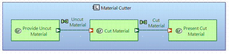
First figure: simply captures the flow of material, handled by the same component. If the way it cuts is one single one, that is, no need to follow a cut pattern or instructions, I think in a simple way is correct. It may be needed to decompose in more logical components.
-
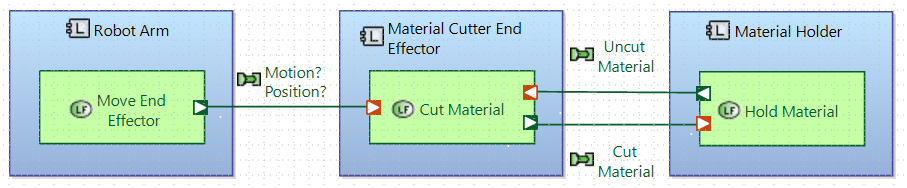
Second figure
- Considering Robot Arm, Material Cutter End Effector (MCEE) and Material Holder Logical Components are part of the same System captured at System Level.
- Material Cutter End Effector is static and just cuts (On/OFF).
I would consider to define the flow from Robot Arm to MCEE as a command Start/Stop as you mentioned “it is, it just needs to start/stop cutting”, and function “Cut Material” only available when Operating (or ON mode).
In any you may have wished to simplify the example, but I believe there will be Actors (Humans) to start the Robot Arm and feed the Material Holder.
I hope that helps.
Logical component names
1 Like
I concur with Helder. And to me, your second schema looks more appropriate with what you are tring to model. In terms of naming your functional echange (the one with “Motion?Position?”, I would consider using an “Event Type” Echange Item, hence the name of your functional exchange could be “Start Cut Signal” meaning that the once the robot arm is at the right position, it is trigerring the start of the cut for the end reflector. You would probably also need a “Stop Cut Signal”. And maybe a function on your end reflector that send information to the robot arm so that he knows when to send the Stop signal (unless it is calculated from the start).
Stephane
2 Likes
Thanks for the feedback @StephaneLacrampe and @HelderCastro.
I did intentionally simplify the model, but let’s build it out to further elaborate the problem, and for fun 
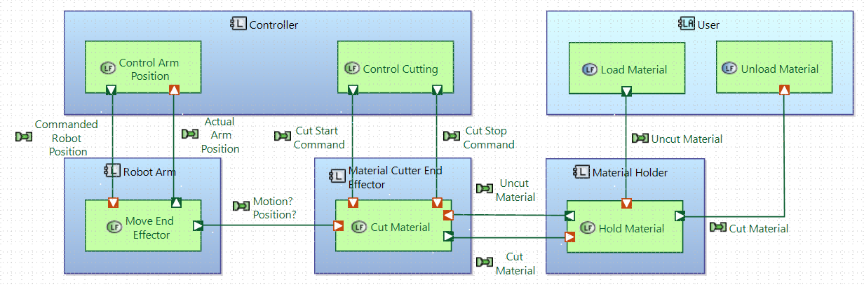
I see what you mean about the start/stop cutting command being sent to the cut material function, but I don’t think it should come from the robot arm. Rather it should come from some logical “controller”. The controller tells the cutter to start/stop cutting, and it also tells the robot arm what position to move to.
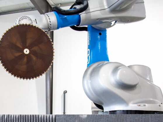
Physically, the end effector is attached to the robot arm. When the robot arm moves its position, the end effector is moved as well, so that it can cut in the right spot (see random google image below). I think I could make this link in the physical architecture, but I’m still not sure what that physical link is “exchanging” between the arm and the end effector, or how to model “why” the end effector is attached to the robot arm in the logical architecture…
Hi @DuWillia,
Great work in your last Logical Architecture diagram.
One aspect to remind ourselves, Logical Architecture captures behavioural components, not physical. Logical Components can be deployed to Physical Nodes in the Physical Architecture, hence, maybe you may need to reconsider what the “Robotic Arm” behaviour might be. Maybe, Robotic Arm is more representative as a physical at the Physical Architecture layer?
Modelling tips (from Define logical components):
- Logical components implement functions that work together to achieve a common goal within a component.
- The important rule to comply with is to force ourselves to exclude all technological considerations or implementation choices.
You may extend the above exercise to all other components.
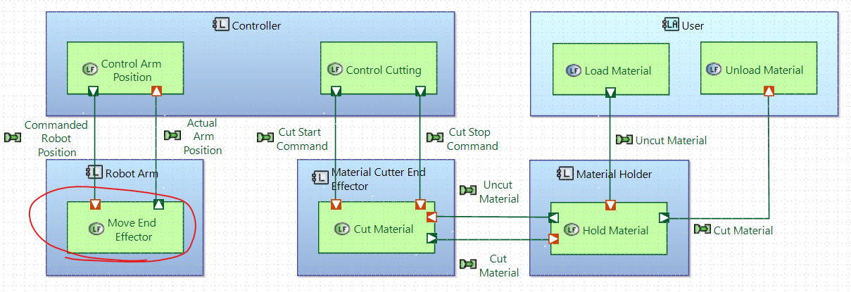
In terms of modelling, I do think the Functional Exchange “Motion Position” should be deleted, as the control commands are flowing from the “Controller”.
However, there may be energy (supply power) flowing from the “Robotic Arm” to the MCEE, and not captured yet?
Physical aspects on how the physical parts are connected I would differ to the Physical Architecture.
I hope that helps,
Hélder Castro
1 Like
I think I understand. So if I have two components (cutter, and robot) that technically function independently and don’t communicate with eachother but are physically connected as part of one assembly, it’s appropriate to leave them disconnected in logical architecture and connect them up with a physical link in the physical architecture.
I do still like the idea of indicating that that the Robot Arm is moving the Material Cutter in the function of the Robot Arm so that it’s clear “why” the robot arm is moving (see red circled function).
Follow up question… does it seem innapropriate to name something “Robot Arm” in the logical architecture? At this point in the logical architecture, we are starting to consider how we want to process, and have selected a robotic arm, but we are not saying which specific type/make/model we will use. I thought it was an important way to document the rough logical idea that could be presented to stakeholders, “some kind of robot arm will move some kind of cutter and cut material on some kind of holder”. Does this seem too restrictive for logical architecture based on your experience?
@DuWillia,
It is quite common to think in the final solution, and how the physical elements will be connected, however, the Logical Architecture (LA) layer can be considered as an abstraction of the Physical Architecture (PA ) and not the final solution.
In addition, allocated functions may be a refinement and a decision made to fulfil needs above captured at System Analysis.
If we follow the below sequence:
-
Logical Functions drive the identification and definition of Logical Components.
-
Interfaces between Logical Components are justified by the functions.
-
Functions can be allocated to Component Exchanges (still behaviour).
-
Components Exchanges can be allocated and transported by a Physical Link.
If there is a justified Physical Link between the “Robot Arm” and the MCEE, then it should be captured.
The why the Robot Arm is moving, may be justified by a program that is following and the control arm position provides this to the Robot Arm. I will leave this for your understanding of the domain and system.
As you mentioned, it does not say what type of arm is and it may capture the correct level of abstraction at this level and to address the communication with the different stakeholders.
I hope it does help,
Hélder Castro
1 Like