Displaying Indirect or Simplified Physical Connections

Hello Capella community,

I’m wondering if there are ways to display indirect connections on diagrams, specifically when I’m looking to limit the amount of detail shown by removing intermediate nodes. For example, I’m capturing the series of physical links and connections along buses that connects several ECUs. I would like to have a simplified diagram that just shows some of the ECUs and the buses. The problem is that the ECUs typically don’t have a single physical link between them, especially when they are physically far apart in the system. If I include every intermediate node, it starts to add a lot of content to the diagram.

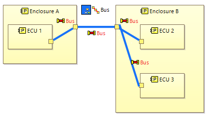
Here’s an example of a setup with 3 ECUs in two different boxes.
image

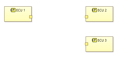
When I remove the enclosures, there aren’t any graphical elements indicating the ECUs are connected.
image

Are there any ways in the tool that I can capture the full series of links/connections but show simplified diagrams with some intermediate elements removed? Any thoughts would be appreciated!

My one idea, which I haven’t tried out, would be to create parent Behavioral PCs that encompass everything in each ECU, and then in my simplified diagram the bus would be represented with component exchanges. Offhand I don’t like this idea, because it involves some duplication in the model. I’d worry it would make it tricky to manage or understand component exchanges, because some would be representative of network connections while others would represent higher-level groupings of component-to-component functional exchanges.

I’m not aware of any automated diagram feature that allows abstraction of physical links or paths into simpler representations. Nor is there the equivalent of the delegation you get with component exchanges.

To get your desired outcome, I can only suggest that you take advantage of the Filtering plugin to create direct physical links between the ECUs that are not part of the usual system definition (i.e. can be tagged for filtering and kept filtered off) that are enabled for your simplified view. This allows better control than hiding/unhiding on each diagram you create.

1 Like

Hi, did you find an answer for this issue ?

I haven’t tried this out in a model, but I started using this concept that could be used here to achieve the desired result, it may be less overhead than using the filtering add-on.

I now model buses with a central node for the bus and will nicely format that node in the diagram. The “vehicle bus” rectangle in the screenshot below is actually the central Node PC for the bus.

image

You could model the bus with a physical path that includes both A) the central bus node with it’s connections to all the nodes on the bus and B) the sequence of cables/connections as modeled in my original post (image below). You then could diagram this in two ways to get both results.

image

  1. For a view that includes all the connections (like the cables/enclosures in my example), do NOT include the bus node (and those connections to all the nodes would not be displayed).
  2. For a view that does not include all the detailed connections, add the bus node into the diagram (and the connections to the bus node would be shown, connecting all the ECUs in my example).