In parts of my physical system, we have a lot of distributed/duplicated controllers in different sections of our system. These could be like 80-90x of the same sensor with the same function (as defined & transitioned in Logical Analysis), located at different physical spots in my system. Functionally and Hardware wise, each of these are the exact same, with the difference being their specific name and potentially what other nodes they interface with (what their physical path & eventual processing node).
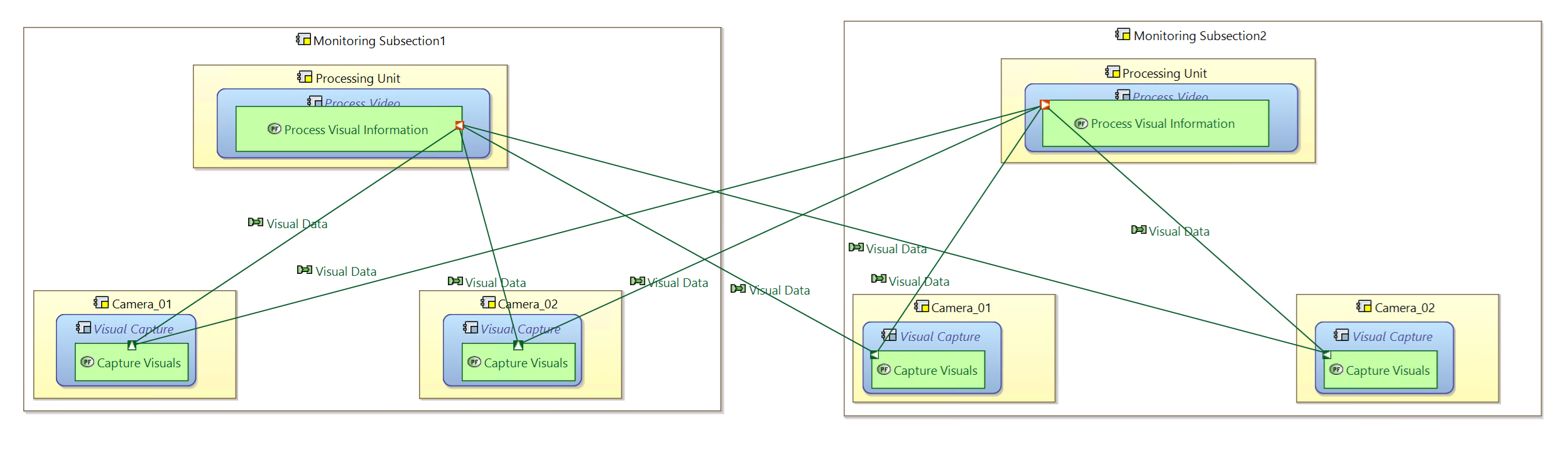
How I would ideally get this modeled would be as shown in the attached image.
I want to know the best way to set up a physical model like this where the Processing Unit PC, the Process Video BC (and all functions) are the exact same similarly with the Camera_01 & Camera_02 in the Monitoring Subsections. I would ordinarily do this in this order:
- Define a Processing Unit REC
- Define Camera REC
- Deploy Processing Unit RPL to Monitoring Subsection; deploy 2x Camera RPL to Monitoring Subsection
- Create Monitoring Subsection REC
- Deploy as many of those as appropriate sections.
The trick is I need to be able to define unique data transmitted from each and every Camera_01/Camera_02 in all Subsections uniquely (e.g. Subsection1_Camera01_Data; Subsection1_Camera_02_Data; Subsection2_Camera01_Data).
Some things I have tried:
- Define Processing Unit/Camera RECs to include the Behavior Module Deployment Link did not work as the back-end same Functional Exchanges did not enable unique Exchange Items it would include all EIs
- Define Processing Unit/Camera RECs that included the Behavior Module, and the Functions did not work as would require manually defining FEs between Processing Units & Cameras in different Subsections (the scale to which I need to do this makes this method highly impractical)
- Define Camera RECs that specifically included only the FE as part of the REC did not work ended up making N-times the number of functional exchanges everywhere.
I could have done my steps wrong somewhere, or may be approaching this in the wrong way (maybe “Interfaces” is the solution…?)… can you help at all? I am pulling my hair out…!
In parts of my physical system, we have a lot of distributed/duplicated controllers in different sections of our system. These could be like 80-90x of the same sensor with the same function (as defined & transitioned in Logical Analysis), located at different physical spots in my system. Functionally and Hardware wise, each of these are the exact same, with the difference being their specific name and potentially what other nodes they interface with (what their physical path & eventual processing node).
How I would ideally get this modeled would be as shown in the attached image.
I want to know the best way to set up a physical model like this where the Processing Unit PC, the Process Video BC (and all functions) are the exact same similarly with the Camera_01 & Camera_02 in the Monitoring Subsections. I would ordinarily do this in this order:
- Define a Processing Unit REC
- Define Camera REC
- Deploy Processing Unit RPL to Monitoring Subsection; deploy 2x Camera RPL to Monitoring Subsection
- Create Monitoring Subsection REC
- Deploy as many of those as appropriate sections.
The trick is I need to be able to define unique data transmitted from each and every Camera_01/Camera_02 in all Subsections uniquely (e.g. Subsection1_Camera01_Data; Subsection1_Camera_02_Data; Subsection2_Camera01_Data).
Some things I have tried:
- Define Processing Unit/Camera RECs to include the Behavior Module Deployment Link did not work as the back-end same Functional Exchanges did not enable unique Exchange Items it would include all EIs
- Define Processing Unit/Camera RECs that included the Behavior Module, and the Functions did not work as would require manually defining FEs between Processing Units & Cameras in different Subsections (the scale to which I need to do this makes this method highly impractical)
- Define Camera RECs that specifically included only the FE as part of the REC did not work ended up making N-times the number of functional exchanges everywhere.
I could have done my steps wrong somewhere, or may be approaching this in the wrong way (maybe “Interfaces” is the solution…?)… can you help at all? I am pulling my hair out…!
Apologies for the unexpected, large image.
Apologies for the unexpected, large image.
Hello Brandon,
I am not quite sure to understand your problem, but I will try to provide an answer anyway.
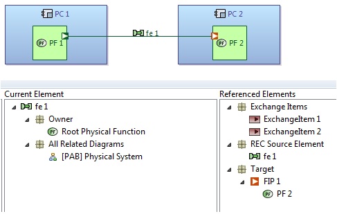
I have created a small example of 2 behavior components having each one function with a functional exchange.
On the functional exchange, I have allocated 2 different Exchange Items.
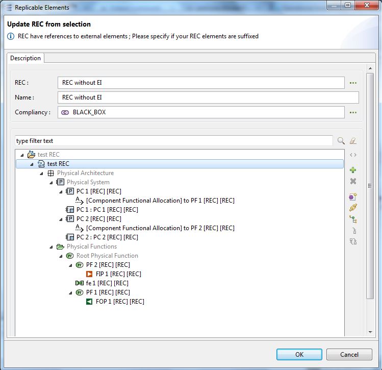
Now on this example, I create a REC from all the elements which can be seen on the diagram (i.e. the components, functions and the functional exchange).
From this REC, if I instantiate a RPL, I will get:
- 2 new components
- the functions in each of the new components
- the functional exchange between the new functions
Please notice than in this case, the new function exchange will refer to the old Exchange Items.
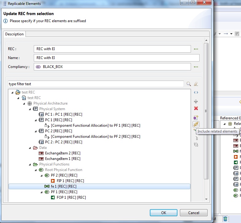
Now if I create a REC which include all elements of the diagram but also the Exchange Items
(for this, you can select the functional exchange and then use the tool “Include related elements”)
If a create a RPL from this new REC, I will get:
- 2 new components
- the functions in each of the new components
- the functional exchange between the new functions
- and 2 new Exchange Items
By the way, the new functional exchange refers to the new Exchange Items
Do you think trying to mix REC including or not part of the Exchange Items could helps answering your problem?
Hello Brandon,
I am not quite sure to understand your problem, but I will try to provide an answer anyway.
I have created a small example of 2 behavior components having each one function with a functional exchange.
On the functional exchange, I have allocated 2 different Exchange Items.
Now on this example, I create a REC from all the elements which can be seen on the diagram (i.e. the components, functions and the functional exchange).
From this REC, if I instantiate a RPL, I will get:
- 2 new components
- the functions in each of the new components
- the functional exchange between the new functions
Please notice than in this case, the new function exchange will refer to the old Exchange Items.
Now if I create a REC which include all elements of the diagram but also the Exchange Items
(for this, you can select the functional exchange and then use the tool “Include related elements”)
If a create a RPL from this new REC, I will get:
- 2 new components
- the functions in each of the new components
- the functional exchange between the new functions
- and 2 new Exchange Items
By the way, the new functional exchange refers to the new Exchange Items
Do you think trying to mix REC including or not part of the Exchange Items could helps answering your problem?